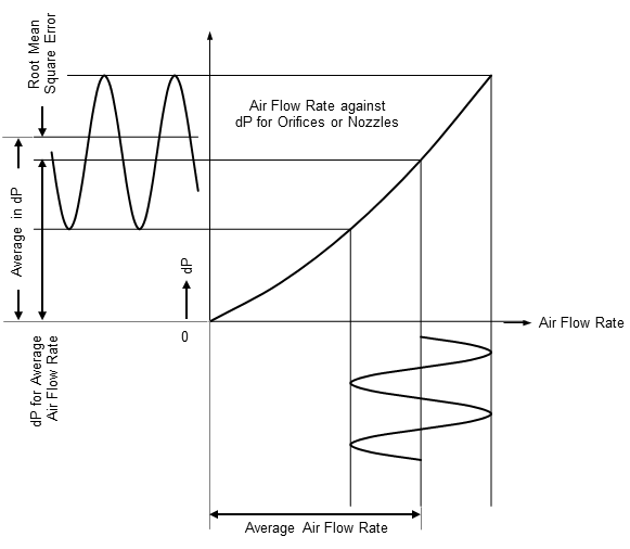
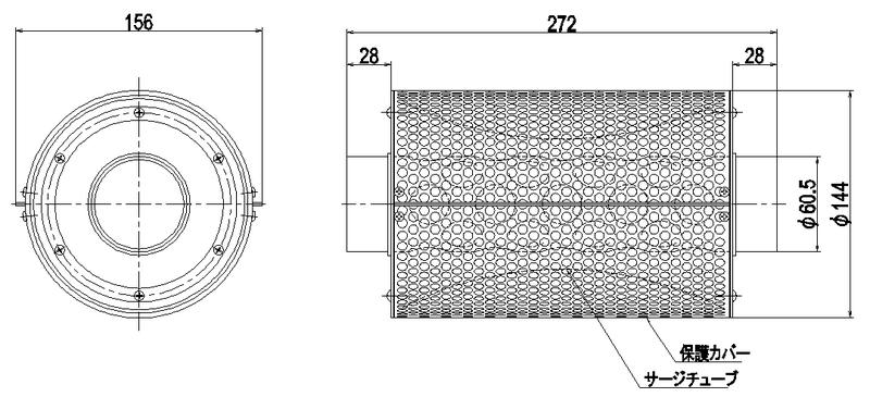
Laminar flowmeter is a flowmeter with linear relationship between the volumetric air flow rate and its differential pressure. The differential pressure in rated flow rate is quite low so it doesn’t affect the characteristics for any test parts. Also the combination of LFEs and LFC-300 does produce no square root errors under the pulsation flow like orifices or round nozzles because of its linear pressure drop characteristics.
Products
Line up
LFE series laminar flowmeters
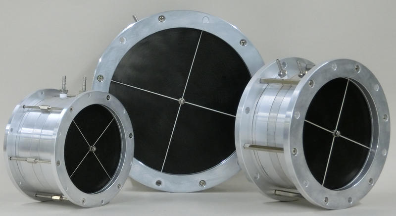 |
B seriesTotal 11 models from 10 to 500 Litre/sec. |
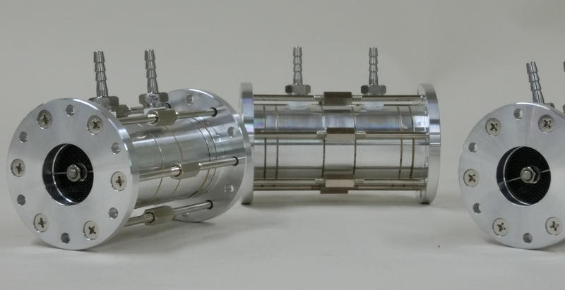 |
LM seriesTotal 9 models from 27 to 1,000 Litre/min. |
Laminar flow calculator model LFC-300
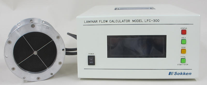 |
|
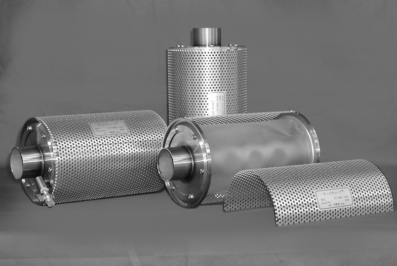
Surge tube ST-300
 |
|
Options
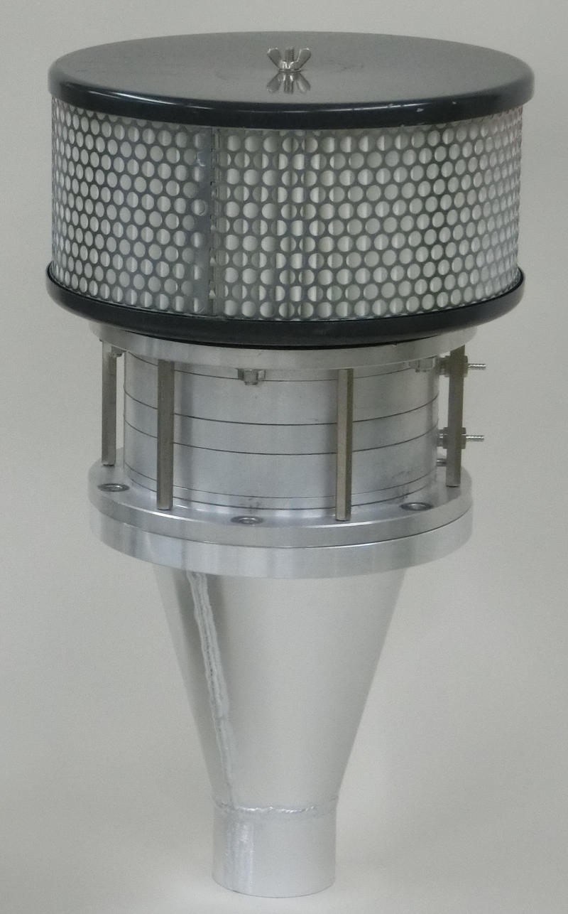
with air filter and duct
|
with upstream/downstream ducts
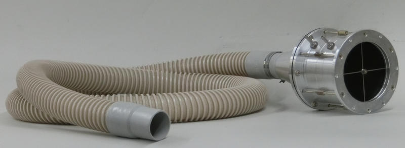
with flexible duct
|
Features
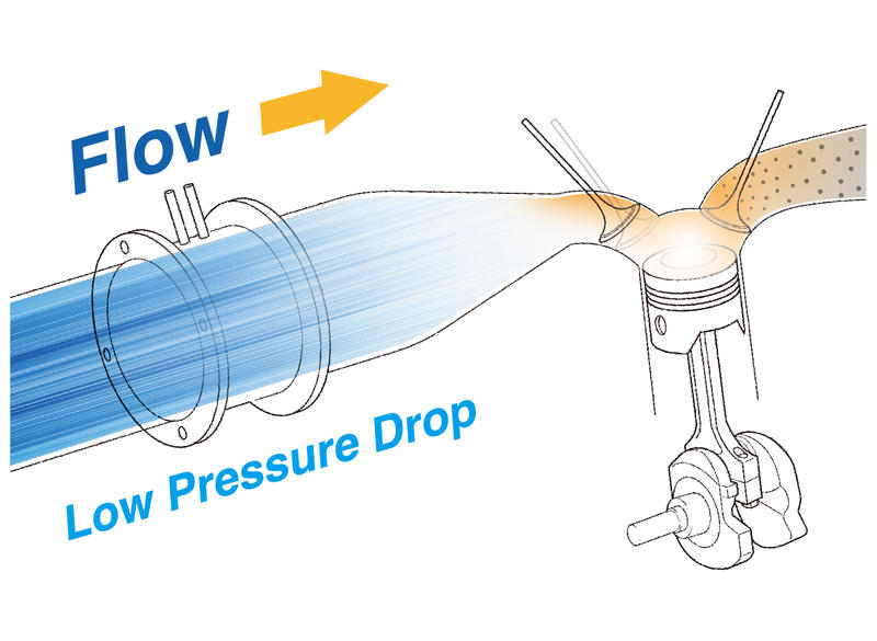
Low pressure drop and high accuracy in flow rate
- Approx 0.8kPa in pressure drop with rated flow
- Accuracy in +/-1%FS within the rated flow
- Accuracy in +/-1.5%FS over 150% rated flow
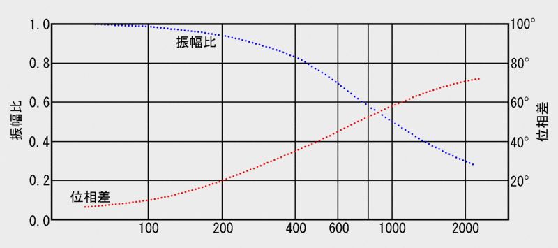
Excellent response time
By assuming pay attention to occur no columnar vibration in the pressure leads with fast response pressure transducer then the
95% amplitude ratio response time can be derived with the pulsating frequency in 150Hz.
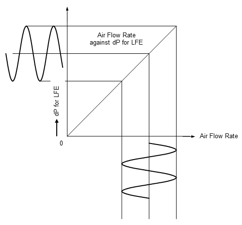
Accurate flow measurement can be made under pulsating flow
The average of the pressure drop fluctuation corresponds to the average of air flow rate since the relationship between volumetric air flow rate and pressure drop is linear.
Laminar flowmetersAverage of pressure pulsation=Average of air flow rate
|
Restriction type flowmeters like orifices or nozzlesaverage of pressure pulsation≠average of air flow rate |
Applications
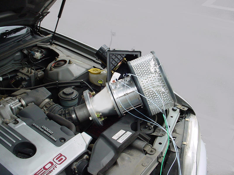
Optimal flowmeter for engine intake air measurement
- Less errors under pulsating flow
- Except the low engine speed or single cylinder engines air flow can be measured without surge tank
- Doesn’t affect the engine performance with its low pressure dropCan be covered the whole engine conditions with its wide dynamic flow range
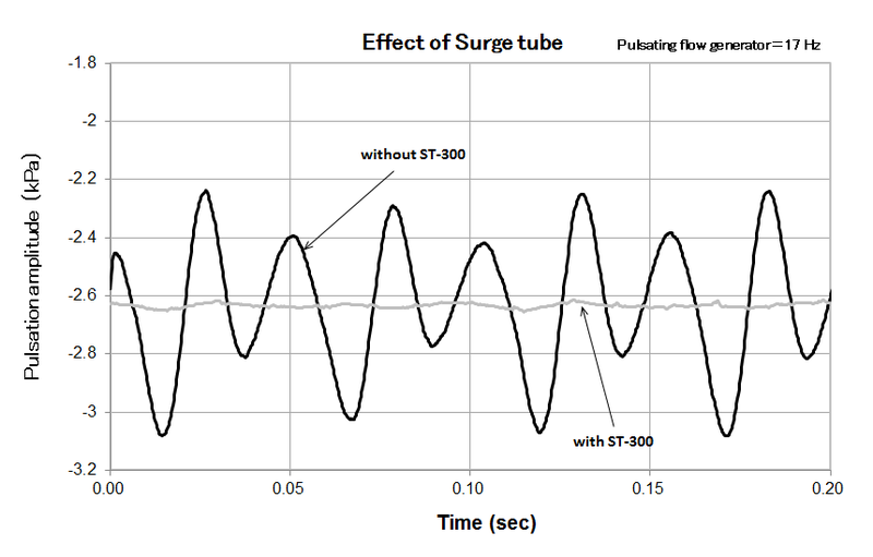
Keep the accuracy good combined with surge tube
The rubber tube volume (approx. 3 litres) in the metal cylinder will change correspond to the pressure so the pulsating flow reduce downstream of the surge tube.
Accurate flow measurement for gas conveyancing system
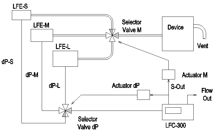
Sokken will recommend configuring the several LFEs, line selector valves and LFC-300 below to measure the wide dynamic flow range accurately.
Because maximum four units of laminar coefficient is able to register into a flow calculator at once, performing a flow measurement is able with an appropriate ranges.
The other applications
- As a calibration tool for various flowmeters
- Evaluate and develop the flow characteristics regarding engines
- Flow measurement for blowers or air compressors
Specifications
| Rated flow rate | Refer to the table in "How to express the model number?" |
| Pressure drop | Approx. less than 0.8kPa at the rated flow |
| Linearity of the pressure drop for flow rate | within +/-1%FS in rated flow and +/-1.5%FS in over 150% rated flow rate |
| Accuracy for the laminar coefficient | within +/-1%FS |
| Allowable line pressure | less than 30kPa |
| Response time | approx. 150Hz (Refer the graph in features) |
| Allowable temperature range | 5 to 50C (without water condensation) |
Note:
An additional differential pressure gauge and a temperature sensor are required to measure the volumetric flow rate.
An additional differential pressure gauge, a temperature sensor and an absolute pressure gauge are required to measure mass flow rate.
Sokken recommend using a laminar flow calculator LFC-300 which equips a differential pressure gauge, a temperature sensor and an absolute pressure gauge.
How to express model number?
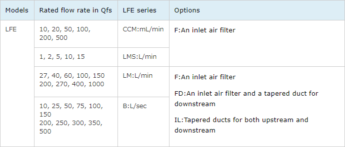
Model number selection guide
LFE-100B-FD Model:B series, Rated flow rate:100L/sec, An inlet air filter and a duct for downstream as options
External view and dimensions
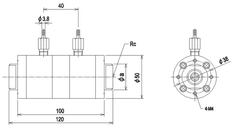
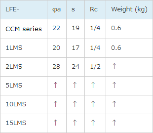
CCM and LMS series laminar flowmeters
Note: The fittings for pressure taps are the common for whole flowmeters
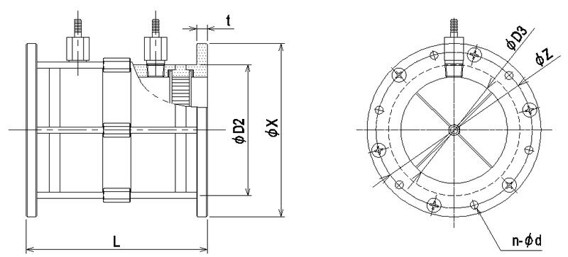
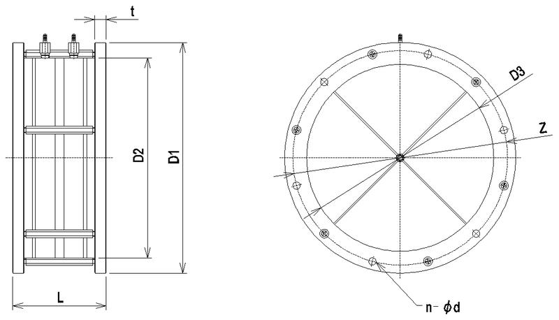
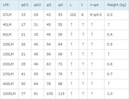
LM series laminar flowmeters
B series laminar flowmeters
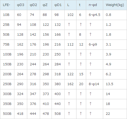
Note: Please refer to the downloaded brochure on this site regarding the detailed dimensions for ducts, air filter and flexible duct etc.
Surge tube ST-300
The nominal connection size for the flexible duct, cuff and wire band is “65”.
FAQ
Which part is the flow rate calculated according to the instruction manual?
It is the volumetric air flow rate at the inlet conditions (pressure and temperature) of flowmeter if calculating the Qreal. It is also the volumetric air flow rate in standard conditions (converting the inlet conditions to 20C, 101.3kPa) if calculating Qnormal.
Where is the best position to measure the temperature and the line pressure?
Near the inlet of flowmeter is the best position for temperature measurement, and recommend the fast response sensor. The line pressure is measured by branching the upstream pressure tap.
What is the lower or upper flow limit for flowmeter?
The lower flow limit is 1/15FS with the high class differential pressure gauge and is 1/10FS with the middle class differential pressure gauge.
The upper flow limit is nearly 1.5 times of the maximum flow.
When the optimum timing for overhaul?
Normally recommend once every year.
Priciple
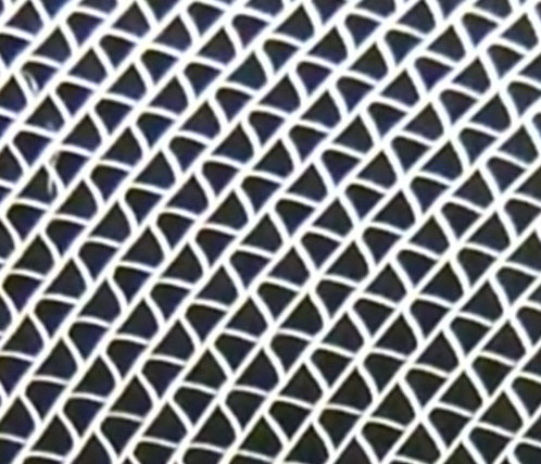
If the flow is laminar flow, the pressure drop across a capillary caused by the viscosity of fluid is proportional to its volumetric flow rate. This is called Hagen-Poiseulle’s law. The laminar flow elements for Sokken’s LFE series flowmeters are configured by bundling multiple trapezoidal cross section flow paths. The fluid flows inside the paths as laminar flow.
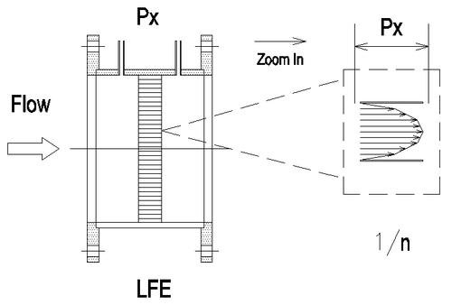
Volumetric flow rate : Q ∝ K × Px
The volumetric flow rate as Qt at the inlet of flowmeter in temperature t is expressed as following equation.
Qt = K20 × (μ20/μt)×Px
where
K20 : Laminar coefficient in standard conditions (P0=101.3kPa, RH=65%)
μ20 : The viscosity of air in 20C
μt : The viscosity of air in tC
Px : The differential pressure for laminar flowmeter
The viscosity of air is a function of air temperature so measuring the air temperature is required.
To calculate the standard volumetric flow rate or mass flow rate from the above flow rate Qt, it is also required to measure the absolute pressure at the inlet of laminar flowmeter.
Calibration
Traceability
Traceability is generally shows the measuring instruments has been confirmed that they are able to reach a National Standards by a calibration chains, and also ensuring a chain of comparisons in the measurement results.The instruments for Sokken’s calibration work use any of the traceable instrument listed below;
- An instrument with "Calibration certificate issued by an ISO/IEC 17025 accreditation bodies with a certified symbol": International traceable instrument
- An instrument with "Calibration certificate according to own technical standard": General traceable instrument
How to calibrate a laminar flowmeter?

The calibration is performed by connecting the same flowmeter models (target LFE-X and standard LFE-std) in series and comparing
each pressure drop by flowing clean air.
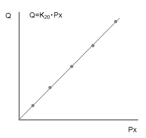
Plotting the flow rate Q calculated from Pstd and the pressure drop for LFE-X, and determine the laminar coefficient of K20 by using least squares method. By using the K20, the relationship between the pressure drop and the flow rate has +/-1%FS linearity within the rated flow rate.
Also plotting K20 and Px for each point, determine the coefficient A and B for K20 as the function of pressure drop in Px. These coefficients are the correction factor for the effect of inlet open ends and are suitable for the precise flow measurement.
GrhC.jpg)
The calculated laminar coefficient K20 and the coefficient A, B is described in the attached data sheet. If using K20 then the flow rate can be simply obtained.
If using the K20 calculated from the coefficient A and B then more accurate flow rate can be obtained.


