Products
Features
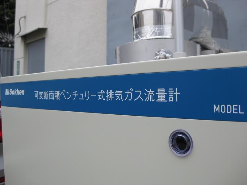
Accurate exhaust gas flowmeter
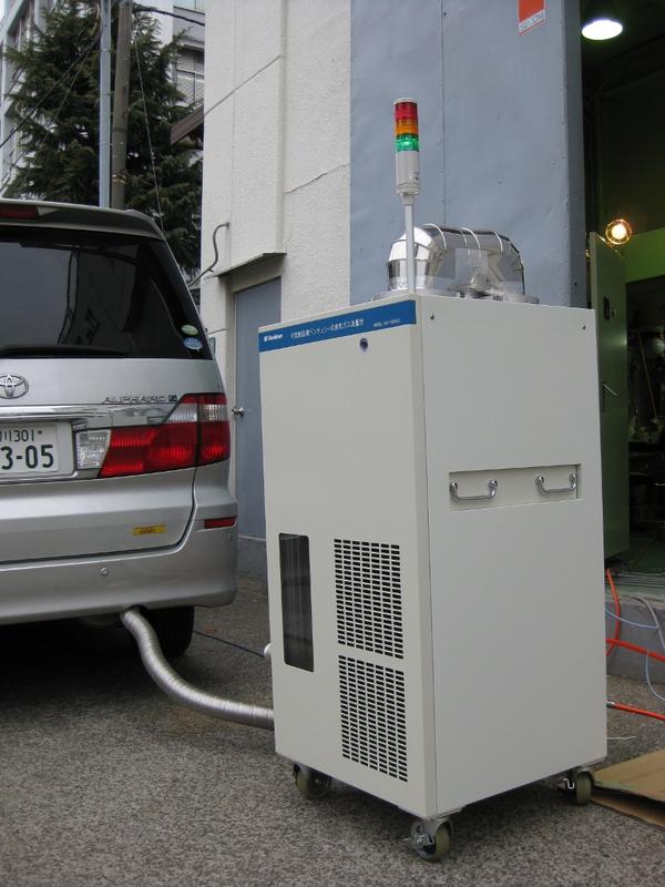
There are several difficulties to measure raw exhaust gas flow rate correctly such as very high temperature exhaust gas with a large amount of moisture, extremely large pulsation flow and a wide flow range. Sokken has performed to measure raw exhaust gas flow rate accurately based on our accumulated experience to measure intake air flow to the IC engines with Laminar Air Flowmeters. The model VAV-EGF6 based on the Venturi-tube flowmeter has several unique functions as follows:
Variable throat area Venturi tube system
The pressure drop across the standard Venturi-tube is normally proportional to the square of flow rate so that the pressure drop may sometimes cause a big problem. Sokken model VAV-EGF6 has solved this problem by changing throat area of the VAV-EGF6 flowmeter. The VAV-EGF6 flowmeter is adjusting a central moving core in proportion to the exhaust flow rate and controls the throat section area quickly of Venturi-tube. By employing this variable throat section area mechanism, the VAV-EGF6 has performed 30 times of flow dynamic range with only 0.5 kPa total pressure drop.
Pulsation flow Attenuator (Surge control tube)A kind of pulsation flow attenuator called "surge control tube"(Utility model registration 3085960, Japan) is equipped to the inlet of VAV-EGF6 in order to control the pulsation flow. This tube consists of Silicone membrane. The surge control tube absorbs exhaust pulsation flow effectively and minimizes the root mean square error in the flow calculation. The surge control tube improves the results at idling conditions or exhaust gas flow from single cylinder engines. |
Specifications
| Principle | Variable throat area Venturi-tube |
|
Rated flow rate |
5.5m3/min (standard specification) the other model is available |
| Exhaust gas temperature | Ambient temperature to 400 C |
| Accuracy | ±3% of measured value |
| Accuracy guarantee range | 1/30 of rated flow rate to rated flow rate |
| Pressure drop | less than 0.5 kPa |
| Response time | 200ms |
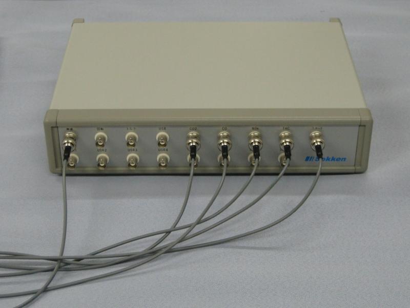
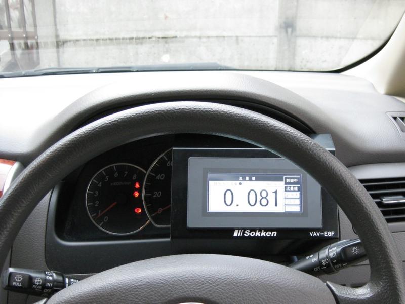
| Analogue output | 0 - 10 VDC |
| Dimensions, Weight | W620×H1250×D600mm,140kg |
| Power, Air supply | 100 V AC 9A, 0.2 MPa compressed air for purge |
| Connections | Inlet port :JIS50A5Kflange Outlet port :JIS100A5KFlange the other connection is available on your request |
Applications
- Modal-Mass measurement
- For controlling Micro-Tunnel
- For controlling Bag Mini-Diluter
FAQ
Is the output(also display) provided as volumetric flow rate or mass flow rate?
The output is provided as volumetric flow rate with converting at 20C 1atm.
Can the system apply to the high temperature exhaust gas exceed 400C?
The high temperature exhaust gas may damage to the surge control tube. It is recommended to cool the exhaust gas temperature down by connecting an appropriate metal tube before the sample line.
How about the durability of silicone membrane in the surge control tube?
It is recommended to replace the silicone membrane every 200 hours.
Gallery
 |
 |
||
 |
 |
Priciple
The principle of the variable throat area Venturi tube flowmeter(VAV) is based on the Bernouli's low for standard Venturi tube flowmeter. The discharge coefficient of standard Venturi tube is a fixed number but it varies for the VAV by the position of central moving core.
The moving core moves to the far right in the sketch when exhaust gas flow through the VAV is minimum flow rate and the effective cross section area also becomes small. According to increase the exhaust gas flow rate through the VAV, the core is moving to a left position and the area of the throat becomes larger.
The position of the moving core is controlled in real-time by responding to the exhaust gas flow rate. In this way, the dynamic range of exhaust gas flow rate can be extended by the VAV.
It is difficult to measure the reverse flow by Venturi tube flowmeters, but the VAV has enabled to measure the pressure drop in stable condition across the Venturi with equipped a pulsation flow attenuator before the VAV.
Features
A wide dynamic range employing a variable throat area Venturi tube
The flow rate from standard Venturi tube is normally proportional to the square root of pressure drop across the Venturi tube so that the 10 times of flow dynamic range is equivalent to the pressure drop of 100 times but the VAV-EGF6 enables to reduce the total pressure drop less than 0.5 kPa by employing the variable throat area Venturi tube with 30 times of flow dynamic range.
Reliable flow measurement together with surge control tube
A surge control tube with silicone membrane is incorporated in the upstream of VAV-EGF to reduce the large pulsation flow(pulsation flow attenuator). This tube absorbs the exhaust pulsation flow effectively and minimizes the root mean square error at the idling condition or for single cylinder engines.
Test results
The chart above is a specimen data taken from a diesel engine exhaust gas measurement. The trace in red was a result from a VAV and the other trace in broken line was a result calculated by the intake air flow. The data shows good agreement for both traces.
Applications
Modal-mass test for diesel exhaust emissions
The modal-mass test is a method to get mass emissions such as CO2 or NOx in exhaust gas from IC engines by multiplying exhaust gas flow rate and volumetric gas concentration for each components and integrating them.
This method has some advantages as below compared with CVS sampling system.
- Easy to get transient engine behaviors due to the fast response.
- Less system/running cost.
The test was carried out by using VAV-EGF exhaust gas flowmeter and LEX-04B smoke meter and measured the mass soot from diesel engine.
Another test was also carried out in order to compare the result from different system with Micro-tunnel and filter paper sampling method.
![]()
Apparatuses
Exhaust gas flowmeter:Sokken model VAV-EGF
Smoke meter:Real-time soot mass smoke meter Sokken model LEX-04B
Test engine:Diesel engine (4 liter)
Test vehicle:Light duty truck (4.8 liter diesel)
Test results
※Please click the graph when expanding.
Test done
Engine and Chassis dynamometer with JE05 drive cycle
Cumulative Soot mass change in JE05 drive cycle
The cumulative mass soot(red) was calculated by multiplying the exhaust flow rate(green) and mass soot concentration(brown) and integrating them. Thus the transient soot mass behavior is easily taken by carrying out the modal-mass test.
Comparison the total soot mass between Micro-tunnel and Full dilution tunnel
The modal mass test is suitable for engine research/development and DPF evaluation as the results have good agreement in the cumulative soot mass and the conventional filter paper soot mass(without SOF).


